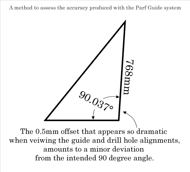
This is a basic method to determine if the holes in a Parf Stick share a linear axis.

None of the four Parf Stick which I have sampled at my workshop seem to have a set of holes that are aligned precisely. The following notes describe a method that I have used to investigate the cause and demonstrate the results.

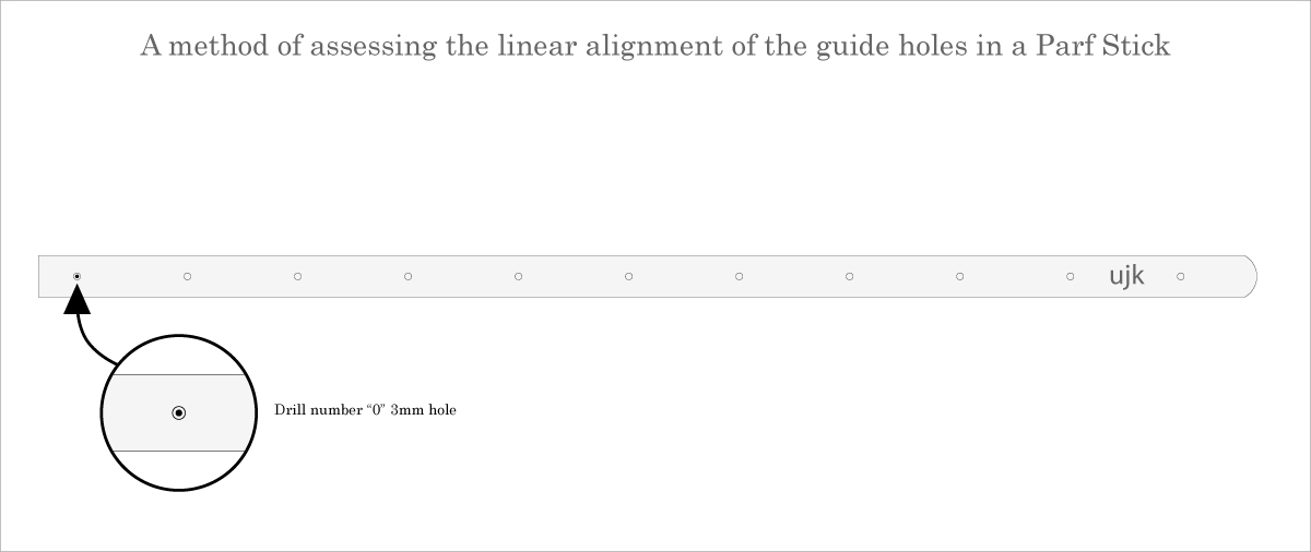
1) Lay the Parf Stick on the table top surface and drill the first 3mm hole.


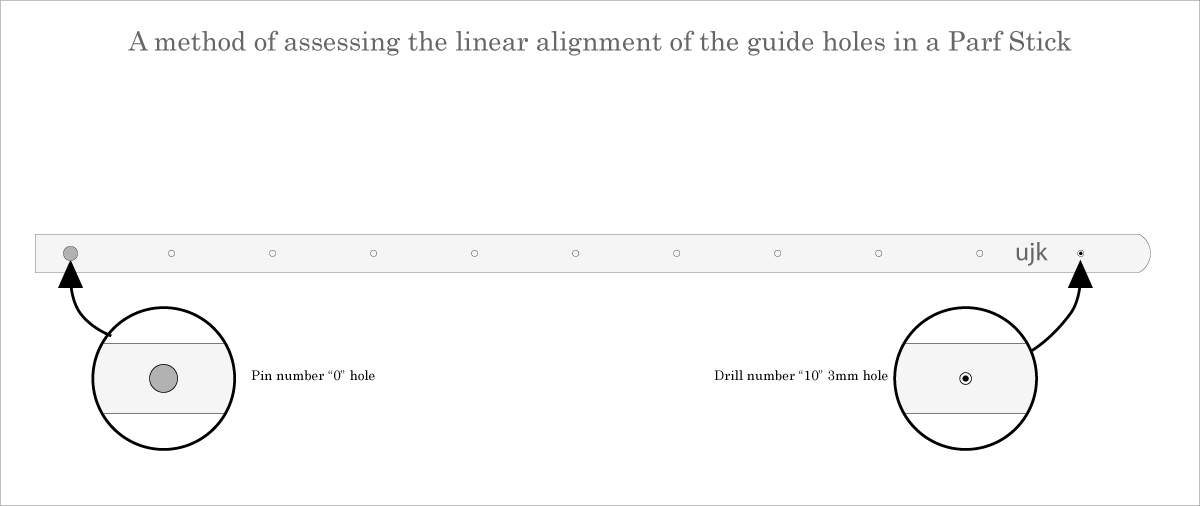
2) Place a pin in hole number "0", and drill the 3mm hole at hole number "10"


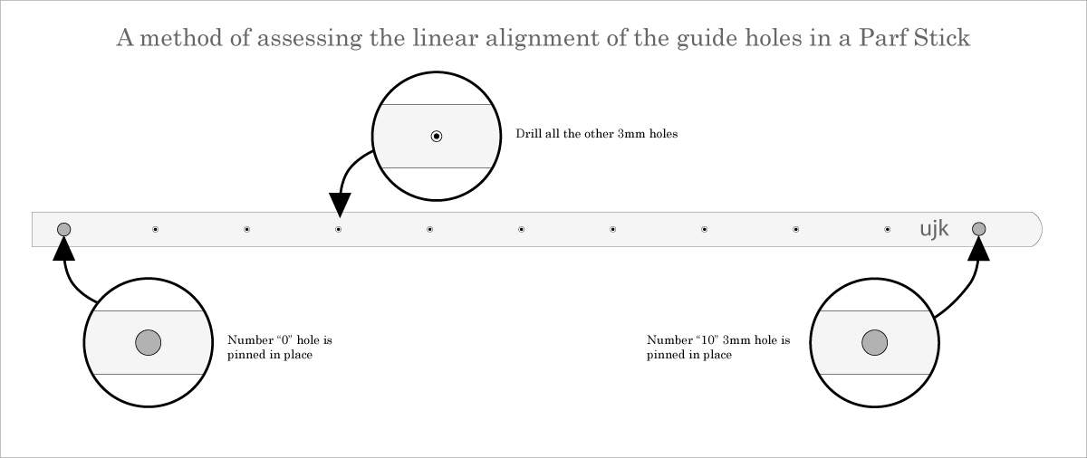
3) Keep the pin in hole number "0", Place a pin in hole number "10", and drill the rest of the 3mm holes. Observe, confirm, and appreciate that the holes appear to be precisely located within the center of the guide holes.


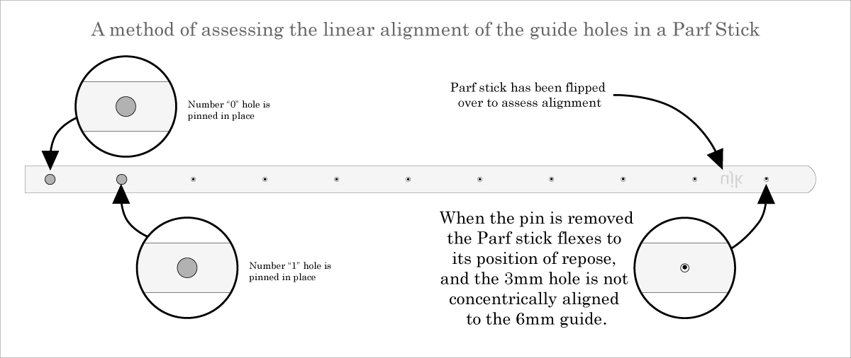
4) Flip the Parf stick over and insert pins at the number "0", "1", and "10" holes. You may find that the third pin fits tightly when it is inserted. This reaffirms the impression that the hole placement is precise.


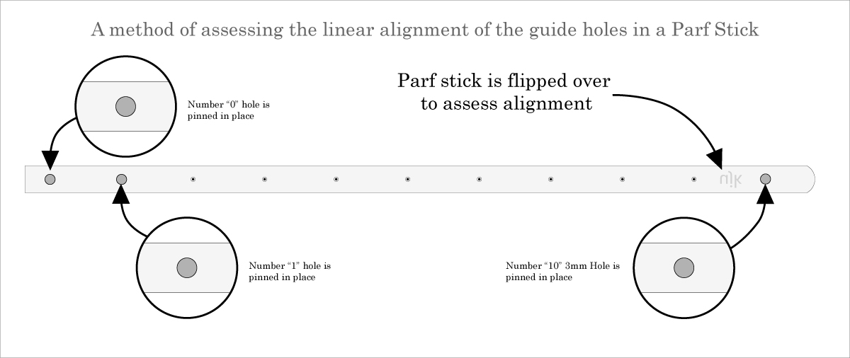
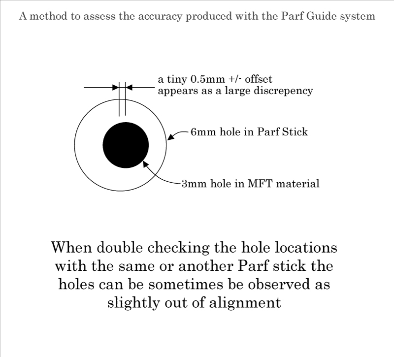
5) Remove the pin from hole number "10" and watch the end of the Parf Stick slide laterally to its natural, at rest position. A misalignment is revealed and it is apparent that the the guide holes are not aligned on a linear axis. When placing the pins, the Parf Stick is flexible enough to be sprung into line so that the guide holes appear to be centered with the drill holes, but when the Parf Stick lays in repose the presumption that the guide holes are placed on a linear axis can not be relied upon.

Please note that misalignment can be observed, in varying amounts, when the pin used in hole number "1" is removed and placed elsewhere along the array. The anecdotal use of the pin in hole number "1" is simply a particular circumstance that I observed just prior to writing these comments.


This is a simplistic analysis that attempts to quantify the ramification of a small deviation in placement of the Parf Stick guide holes

The intention is for each 3mm drill hole to be perfectly centered in the Parf Stick guide holes


At first glance, immediately after drilling the holes, the placement appears perfectly centered, but if you swap out the Parf sticks or flip the sticks over you will notice that the holes do not seem precisely aligned. The system, founded upon a theorem, is intended to be capable of precision but the results indicate that something is causing numerous slight misalignments.

Deviations as small as a fraction of a millimeter are easy to recognize when the circles are no longer concentric


The Pythagorean Theorem, and more specifically a Pythagorean "Triple", is used by the Parf Guide system to layout a grid based upon units of 96mm. The system is referenced to a right triangle with the dimensions shown below.


The value of a 0.5mm deviation, as used in this example, can be factored into a simple trigonometric function to reveal the angular deflection.


In this example, the resulting 90.037 degree angle may seem trivial but the 0.5mm is easy to spot if you place a square against the Parf dogs or check a work piece cut with use of the Parf grid.


The misalignments may seem tiny on a modestly sized MFT grid, but become exaggerated and unpredictable as the grid is extended across a 4 foot by 8 foot sheet of Medium Density Fiberboard. Of greater concern is the fact that each of the errors committed in a series of cuts based upon the misaligned grid will accumulate. A sheet cut on such a grid will quickly deviate from square, and become some sort of randomly shaped polygon.

In practice, I have found the deviations occur in various directions. While they tend to become pronounced at the widest margins of the grid layout, the issues are apparent throughout the grid depending on what you choose to use as the base reference or "origin" point. The condition is exasperated if the grid was laid out with a mix and match use of the Parf Sticks, as the discrepancies in each do not seem consistent.

Subsequent measurements, made by using the Parf Sticks and the pins are frustrated by the very same inconsistencies. The observation of a misalignment may be attributed to the drill hole placement, the guide hole placement, or most likely a combination of both.

A concern regarding unpredictable precision seems relevant as it is likely that any combination of holes in the MFT grid will be relied upon at some point in the service life of the work table.

The lateral rigidity of the Parf Sticks is insufficient, yet the spring effect of the steel material confounds the realization that the issue is problematic. The flexibility of the stick allows for the successful the insertion of registration keys, such as the supplied pins. This capability would seem to confirm that the system produces precise results, but the elasticity of the material actually accommodates the imprecision.

I suspect that the flexible characteristic undermines the effort to achieve precision during manufacture, and believe that it inhibits the ability to implement precision when using the Parf Sticks in the manner in which they are intended.